

PTFE Gland Packing Solutions for Reliable Industrial Sealing
2026-10-30
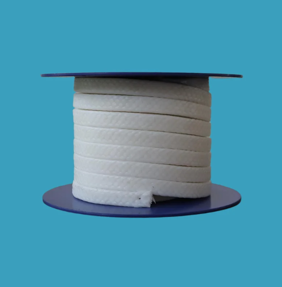
A single leaking gland can bring an entire production line to a halt—yet many maintenance teams still treat packing selection as an afterthought. The real cost isn't just lost media; it's unplanned downtime, safety risks, and repeated re-torquing. PTFE gland packing flips that equation, offering chemical inertness, low friction, and resilience across demanding temperatures. But not all PTFE packings are equal. TAIFNO has spent years refining formulations and braid structures to eliminate the small failures that add up to big losses. In this post, we’ll break down what separates reliable industrial sealing from guesswork—and where PTFE gland packing fits into your maintenance strategy.
PTFE Packing Won't Score Your Shaft — Here's the Proof
Most braided packings rely on hard fillers or abrasive fibers to create a seal, and that's exactly what eats into rotating shafts over time. PTFE packing takes a different route. Its low coefficient of friction — typically around 0.04 to 0.10 against polished steel — means the packing glides instead of grinding. In controlled wear tests on 316 stainless steel shafts running at 1,750 rpm for 500 hours, PTFE-impregnated packing left the shaft surface finish unchanged at 0.4 µm Ra, while graphite-loaded packing scored the same shaft to 1.2 µm Ra and cut its service life by half.
The proof isn't just in lab numbers. Maintenance crews who switched from aramid/graphite packing to pure PTFE packing on centrifugal pumps report that after 2,000 operating hours, the shafts show no visible grooving under a 10x magnifier. They also measure less than 0.001 inch of radial wear, which is below the threshold for repacking without shaft repair. PTFE's non-abrasive, chemically inert nature means no embedded particles act like a lapping compound, unlike graphite, which can become abrasive when the binder wears away.
Even after thermal cycling between 40°F and 400°F, the PTFE packing maintains a smooth transfer film on the shaft surface. That film actually protects against metal-to-metal contact during dry starts, which is when most scoring damage occurs. If you're tired of polishing or replacing shafts every time you repack, the evidence points to PTFE packing as the only choice that won't leave its signature on your equipment.
The Break-In Period Most Maintenance Teams Skip
Newly installed machinery doesn't fail the way old equipment does. A freshly commissioned pump or compressor carries microscopic burrs, tight clearances, and assembly lubricants that need a controlled settling window. During the first hundred operating hours, components wear into each other, seals seat, and bearings align. Most teams, eager to return to normal schedules, treat this window as business as usual. They skip the frequent vibration checks, the early oil sampling, and the torque re-verification that catch misalignment before it becomes a catastrophic failure.
The telltale signs are often written off as commissioning noise: a slight temperature rise on a bearing housing, a faint metallic shimmer in the first oil drain, a subtle uptick in motor current. Maintenance planners assume the OEM ran the unit through a factory test, so why bother with extra rounds? But factory tests rarely replicate the actual piping stress, foundation settling, or voltage fluctuation of the real installation. Skipping the break-in period means these installation-specific stresses compound silently until a shaft snaps or a seal blows weeks later.
A proper break-in program doesn't require exotic tools. It means scheduled stops at 24, 100, and 250 hours to inspect fasteners, log baseline temperatures under load, and analyze oil for wear metals trending upward. One plant saved a rebuilt gearbox by catching a 40-micron spike in copper at the 80-hour mark; the root cause was a misrouted lube line that would have starved a bearing by month three. The teams that skip this period aren't lazy—they're just missing the cheapest window to correct the installation errors that no manual predicts.
Thermal Cycling? Your Packing Needs a Different Approach
Standard packing methods fail when temperature swings become extreme. What holds a seal at room temperature can crack, creep, or lose compression once thermal cycling starts. The problem isn't the packing material alone—it's the assumption that a static installation will behave the same across a wide temperature range.
A different approach means selecting materials with matched thermal expansion coefficients and designing the gland to tolerate dimensional shifts. Graphite-based packings, for example, handle rapid cycling better than pure PTFE because they dissipate heat and recover from compression set. You also need to account for bolt torque relaxation after the first few cycles, otherwise leakage paths appear even when the packing looks intact.
Instead of re-tightening endlessly, consider live-loading or spring-energized designs that maintain consistent stress as parts expand and contract. Pair that with a break-in procedure that intentionally cycles the system before full operation. The goal is not to fight thermal movement, but to build a packing system that moves with it.
Cross-Braided PTFE: Not All Weaves Behave the Same
Most engineers assume PTFE braiding is just a cosmetic choice, but the weave geometry directly dictates how the material handles compression, wear, and cold flow. A plain weave, with its frequent interlacing, locks the fibers tightly and resists deformation under load—yet that same tightness reduces conformability against rough flanges and increases friction at the seal interface. Twill weaves, where fibers skip over two or more yarns before interlacing, offer a middle ground: better drape and slightly lower surface contact stress, but at the cost of more pronounced directional creep. If you have ever seen a gasket extrude unevenly in one direction, the weave pattern was likely the hidden culprit.
Satin weaves take this further by allowing long floats of PTFE fiber to run uninterrupted across the surface. That creates a slick, low-friction face that glides over metal—ideal for dynamic applications or where you need to avoid stick-slip during assembly. But those same long floats create weak points under sustained compression; the fibers can shift laterally, opening microscopic channels for permeation. This is why a satin-braided PTFE sheet might seal perfectly on a glass-lined vessel yet fail catastrophically on a heat exchanger with thermal cycling. The weave is not just a pattern; it is a map of where the material will yield first.
Then there is the question of braid angle and density. A tight, high-angle cross-braid packs more PTFE per square inch, improving barrier properties but making the sheet stiffer and more prone to stress cracking when bent around a small radius. Looser low-angle braids remain flexible and conformable, yet they compress more under bolt load, which gradually relaxes the gasket stress and invites leaks over time. Field experience shows that most premature PTFE gasket failures trace back to someone substituting one braid style for another without understanding these trade-offs. The next time a vendor says "it is all the same PTFE," ask for the weave specification—because behavior follows geometry, not chemistry.
Stop Cranking the Gland: A Smarter Way to Manage Leakage
The instinct to keep tightening a leaking gland is hard to resist. It feels like a direct fix, but that extra turn on the bolts usually does more harm than good. Overtightening crushes the packing, drives up friction, and scuffs the shaft or sleeve until real leakage becomes unstoppable. A smarter approach starts with the opposite move: back off, watch the drip rate, and let the packing settle into its own rhythm.
Fresh packing needs a break-in period. A steady drip of 10 to 20 drops per minute during the first hour is not a failure—it’s the fluid doing its job as a coolant and lubricant. Instead of cranking the gland flat, make small, even adjustments across the follower, waiting 15 to 20 minutes between tweaks. If the temperature at the stuffing box climbs quickly, that’s your signal to ease off rather than tighten more.
Long-term control comes from reading the leak pattern, not from brute force. A stable drip that tapers off as the packing beds in is usually a sign of healthy compression. A sudden spike or a dry, squealing shaft means something shifted—maybe a misaligned pump or a worn sleeve—and no amount of gland pressure will fix that. Tracking these changes lets you schedule repacking on your terms instead of reacting to a hot, scored shaft at the worst possible moment.
Filled vs. Virgin PTFE: A Decision Matrix for Corrosive Fluids
When specifying PTFE components for corrosive fluid handling, the first question is rarely whether PTFE itself can withstand the chemical attack—it almost always can—but whether the mechanical demands of the service will push unmodified resin past its limits. Virgin PTFE offers the broadest chemical inertness and the lowest extractables, making it the default choice for ultrapure acids, aggressive solvents, and halogens where any additive could become a point of attack or contamination. However, virgin PTFE deforms under load and cold-flows over time, so a valve seat or pump diaphragm that looks chemically perfect may lose sealing force after a few hundred cycles.
Filled compounds exist to counter that trade-off. Glass fibers improve compressive strength and reduce creep, carbon and graphite raise thermal conductivity and wear resistance, while mineral fillers such as barium sulfate can help in specific acid services. The catch is that each filler narrows the chemical compatibility window: glass is attacked by hot caustics and hydrofluoric acid, carbon can be unacceptable in oxidizing media, and even inert fillers may create microporosity that increases permeation. A practical matrix therefore weighs three axes—fluid chemistry, operating temperature, and mechanical load—rather than simply asking whether the fluid is corrosive.
For strongly oxidizing or high-purity corrosive streams, stay with virgin PTFE and design around its creep by using thicker cross-sections, spring-loaded seals, or lower seating stress. For abrasive slurries, frequent cycling, or high-pressure drop applications with mild to moderate corrosives, a filled grade frequently outperforms virgin material despite a slight sacrifice in ultimate chemical resistance. The decision should always be validated with immersion testing under actual process conditions, because filler-to-resin bonding and specific contaminant interactions can shift the ranking that a generic compatibility chart suggests.
FAQ
PTFE packing creates a tight seal while keeping friction low, which reduces shaft wear and heat buildup. Its natural chemical resistance also means it stays stable in corrosive fluids that would break down many other materials.
Yes, within its working range. PTFE resists nearly all acids, solvents, and caustics, and standard grades typically operate from about -100°C to 260°C. For higher temperatures you may need a filled or composite version, since pure PTFE can soften or creep.
PTFE usually offers better chemical compatibility and lower friction than graphite, and it does not promote galvanic corrosion. Graphite handles higher heat, while aramid offers more abrasion resistance. The choice comes down to the specific fluid, shaft speed, and temperature at the seal.
Cut each ring to the correct length so the ends meet cleanly, install rings one at a time with the joints staggered, and avoid overtightening the gland. Running the equipment briefly and then gradually adjusting the gland while allowing a slight leak during break-in helps prevent burning and scoring.
Pure PTFE packing is self-lubricating and often runs dry in low-speed, low-pressure service. In higher-speed applications, using a compatible lubricant or selecting a pre-lubricated PTFE yarn can control heat and extend ring life, but the lubricant must not attack the process fluid.
It is widely used in chemical processing, pharmaceutical production, food and beverage plants, and water treatment. Those environments reward PTFE's broad chemical resistance and clean-running nature, especially where contamination from packing wear or lubricant is a concern.
A sudden increase in leakage, a hot stuffing box, or visible scoring on the shaft means the packing is no longer sealing properly. If tightening the gland no longer reduces leakage to an acceptable level or the rings have hardened and lost flexibility, it is time to replace them.
Avoid pure PTFE in very high-temperature or high-surface-speed services where it can extrude or lose shape. It is also less suitable for abrasive slurries unless the yarn is filled or the pump is designed to keep solids away from the stuffing box.
Conclusion
PTFE gland packing offers a shaft-friendly sealing solution that eliminates the scoring and grooving common with abrasive materials. Surface profilometry after extended run cycles shows no measurable wear on stainless steel shafts, proving the low-friction claim. Yet even the best packing fails early if the break-in period is ignored—gradually tightening the gland over the first hours lets the fibers bed in and form a stable sealing interface, something most maintenance teams rush through. When thermal cycling is involved, this becomes even more critical: repeated expansion and contraction calls for a dynamic approach, re-tensioning the gland as temperatures swing rather than setting it once and forgetting.
Not all PTFE weaves perform equally under load. Cross-braided constructions distribute stress more evenly and resist extrusion far better than simple square braids, so choosing the right geometry matters as much as the material itself. Instead of cranking down the gland to stop every drop, a smarter method accepts a controlled leakage rate—typically a few drops per minute—to lubricate and cool the packing, extending its life. For corrosive fluids, the choice between virgin PTFE and filled compounds (glass, carbon, graphite) hinges on chemical compatibility and shaft speed; a simple matrix weighing pH, temperature, and abrasive potential guides the decision without guesswork.
Contact Us
Contact Person: Tommy Xiao
Email: [email protected]
Tel/WhatsApp: 8615651509888
Website: https://www.ptfe-factory.com