

IEC Standard Busbar Insulator Essentials for Safe Electrical Installations
2026-09-20
Most electrical failures never start with a loud bang—they begin quietly, in a busbar support that wasn’t built to the right standard. If you’ve ever wondered why IEC compliance matters for busbar insulators, or how the wrong choice can derail an entire installation, you’re in the right place. MOLDVOLT has spent years on the front lines of safe electrical design, and this guide distills the essentials without the fluff.
Choosing Insulator Materials That Align With IEC Thermal and Mechanical Ratings
Insulator selection starts with matching the thermal class to the expected hot-spot temperature, not just the average winding rise. IEC 60085 defines thermal endurance classes, and a material rated Class F (155°C) may seem adequate until you account for overloads, harmonic heating, or poor ventilation; pushing a Class F material to sustained 160°C operation shortens life disproportionately. Check the relative temperature index (RTI) and halving interval from the material datasheet rather than relying solely on the class letter.
Mechanical ratings matter just as much because thermal aging often embrittles polymers before dielectric failure appears. IEC 60672 and related test methods specify flexural, tensile, and compressive strengths at room temperature and after heat ageing. For busbar supports or coil separators, compare the expected short-circuit forces and vibration loads with the aged strength values, not the virgin values. A material that shows a 40% drop in flexural strength after 5,000 hours at rated temperature may fail mechanically even if its dielectric strength remains acceptable.
Finally, consider the interaction between thermal and mechanical stress. CTE mismatches with copper or steel can create cracks at interfaces during thermal cycling. Prefer materials with low moisture absorption and good tracking resistance if the insulator will see condensation or pollution. Request test reports that include both IEC thermal endurance and mechanical endurance data under your specific load profile, rather than generic catalogue values.
Calculating Creepage Distances for Polluted Service Conditions
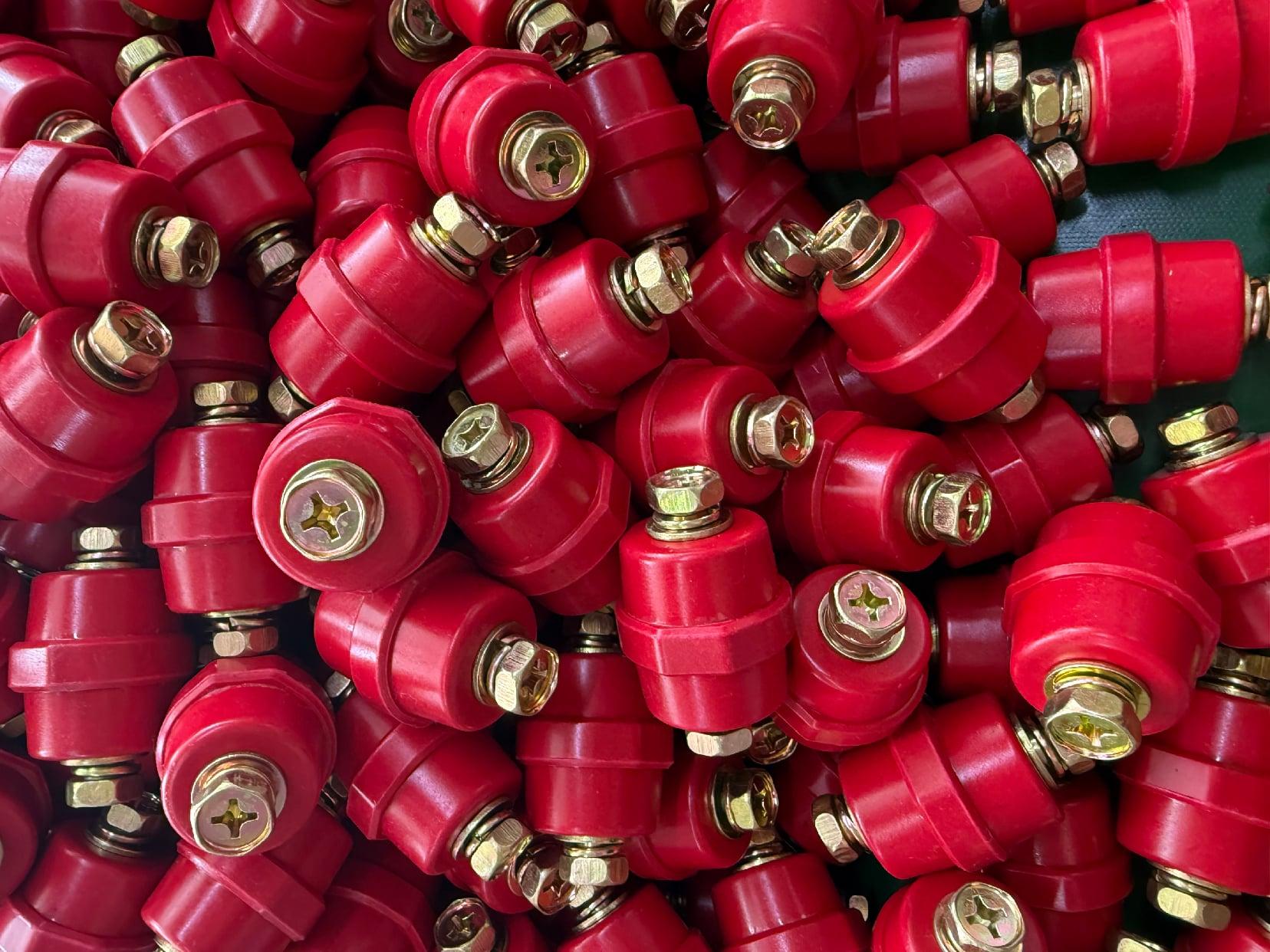
When insulation surfaces are exposed to dust, moisture, or chemical residues, the air gap alone no longer guarantees safety. Engineers begin by identifying the pollution degree of the service environment, typically ranging from clean indoor conditions to heavy conductive contamination. Once the pollution degree is known, the required creepage distance is determined from tables in standards like IEC 60664-1, which link rated voltage, insulation material group, and environmental severity. The material group matters because some polymers resist tracking better than others, allowing shorter creepage paths for the same voltage stress.
A practical approach starts with the RMS working voltage across the insulation, then applies a multiplication factor derived from the selected pollution degree. For example, a circuit operating at 400 V in a lightly polluted factory might need a creepage of 6.3 mm, but the same voltage in a heavily polluted outdoor installation could demand over 12 mm. These numbers are not arbitrary; they reflect long-term test data on how surface leakage currents develop into carbonized tracks. Designers often add extra margin when the actual contamination pattern is uneven, such as areas near cooling fans or cable entries where dust accumulates faster than elsewhere.
It is also worth noting that creepage distance interacts with the shape of the insulating surface. Ribs and grooves can increase the effective path length without enlarging the component footprint, a technique often used in high-voltage connectors and standoff insulators. However, if the grooves are too narrow, they may fill with conductive debris and become ineffective. Comparing calculated values against actual field failures remains the most reliable way to validate a design, especially when service conditions differ from standard test setups.
Bolt Torque Specifications That Avoid Insulator Stress Fractures
Torque values for insulator bolts look like standard hardware specs, but they are tuned to a different failure mode. The goal is not just clamp load; it is to keep the metal flange from pressing unevenly into the porcelain or polymer core. Once a fastener crosses the safe band, the tensile stress at the base of the shed or at the metal-ceramic interface climbs sharply, and microcracks can start long before the bolt yields.
A good rule is to treat the manufacturer's chart as a hard limit, not a starting point. Dry zinc-plated threads on a 12 mm bolt might call for 25–30 N·m, while the same bolt with anti-seize often needs 20–25 N·m to avoid overloading the joint. Station post insulators and transmission bushings sit higher, sometimes 50–65 N·m for larger diameters, but the drop-off in margin is steep if you guess or use impact tools.
The sequence matters as much as the number. Tighten opposing bolts in two or three passes, and recheck after the first thermal cycle or a few days of vibration. If you find a loose fastener, resist the urge to give it an extra quarter turn unless the chart explicitly allows that. A calibrated torque wrench with a known error band is non-negotiable here, because the difference between safe and cracked is often less than 10% of the target value.
Pre-Commissioning Voltage Withstand Tests for Busbar Insulators
Before a busbar system is put into service, the insulators must undergo a voltage withstand test to confirm they can handle the operational stress without breaking down. The test typically applies a specified AC or DC voltage—often higher than normal operating voltage—across the insulator between the live busbar and the grounded support structure. This is done for a set duration to reveal any hidden defects like cracks, voids, or contamination that might not be visible during a visual inspection.
The actual test voltage and duration depend on the insulator's rated voltage and the applicable project specification. For medium-voltage switchgear, it is common to use an AC hipot test at a voltage derived from the system's nominal level, while DC tests are sometimes preferred in the field because the test set is lighter and easier to transport. Regardless of the method, the insulator should not flash over or show a sudden rise in leakage current. Even small partial discharges that persist during the test can be an early warning of future tracking or puncture failure.
After the test, the insulators should be inspected again, and any that exhibited abnormal leakage current or surface flashover are rejected or cleaned and retested. The test report should record the ambient conditions, applied voltage, duration, and measured current. Passing the pre-commissioning withstand test is a key hold point before energizing the busbar, because a weak insulator can cause a phase-to-ground fault once the system carries load.
Early Warning Signs of Surface Tracking and Erosion
Surface tracking and erosion often begin with subtle changes that are easy to overlook. A faint, irregular carbonized path may appear on insulation surfaces, especially near terminals or areas of high electrical stress. You might notice a slight discoloration or a chalky, powdery residue forming along the creepage path. Over time, this can develop into a roughened, pitted texture that catches light differently than the surrounding material.
Another key indicator is intermittent leakage current or unexpected minor arcing during humid conditions. Thermal imaging may reveal localized hot spots that don't align with normal load patterns. If the insulation surface starts to feel tacky or develops microcracks, it's a sign that degradation has already progressed. Regular visual inspections under adequate lighting can catch these early stages before a full dielectric failure occurs.
Inspection Frequencies Tied to Environmental Pollution Class
How often a facility gets inspected depends heavily on its pollution class designation. Regulators don't apply a one-size-fits-all calendar; they sort operations into categories based on potential environmental impact, then adjust visit schedules accordingly. A high-risk chemical plant might face quarterly walkthroughs, while a small dry cleaner with minimal solvent use could go two years between routine checks.
The logic is straightforward: scarce inspector hours should flow toward the sites most likely to cause harm. But the classification itself isn't static. A facility's history of violations, complaints from neighbors, or shifts in production volume can push it into a more frequent inspection tier. New permits often start with tighter monitoring, then relax once the operator demonstrates consistent compliance over several cycles.
Some jurisdictions publish the multipliers publicly, so a Class A polluter might get inspected three times more often than a Class C. Still, real-world schedules can deviate due to staffing shortages or emergency response demands. For operators, understanding where they sit in the pollution class hierarchy often matters more than reading the formal inspection policy—it determines whether they'll see an inspector every few months or only when something goes wrong.
FAQ
Because their failure doesn't just stop power flow—it can trigger arc flashes, fires, and cascading damage. Under IEC 61439-1, busbar insulators are part of the assembly's protective scheme, not passive accessories. They must maintain separation under thermal cycling, short-circuit forces, and aging while keeping touch-safe clearances. A cracked or tracked insulator can become a conductive path, so the standard requires type-tested combinations, not isolated parts.
Clearance is the shortest path through air between two live parts, while creepage is the path along the surface of the insulator. Pollution and humidity reduce the surface's insulating ability, so creepage requirements are usually larger. IEC 60664-1 links creepage to pollution degree and material group: for example, a 690V system in pollution degree 3 may need over 10mm of creepage, while clearance might be only 8mm. Picking an insulator with only adequate clearance can lead to tracking and flashover.
Not reliably. A higher rated voltage often implies larger physical dimensions, but the creepage requirement is driven by the working voltage, overvoltage category, and pollution degree—not the insulator's maximum voltage alone. If the surface is too short for the actual environment, contamination will bridge it regardless of the nameplate rating. Always check the creepage spec against your system's RMS voltage and expected pollution, not just the kV class.
Short-circuit forces are the main killer. The peak electrodynamic force between parallel busbars is roughly proportional to the square of the peak current and inversely proportional to their spacing. For a 50kA peak on bars 100mm apart, the force can exceed several thousand Newtons per meter. Insulators must handle that without cracking, and their support spacing needs to match the busbar's bending strength. Also consider thermal expansion: rigid mounting with no allowance for bar growth can shear the insulator.
Absolutely. Over-torquing a bolt through a glass-fiber-reinforced epoxy insulator can create micro-cracks that grow under thermal cycling, eventually causing a mechanical failure. Under-torquing lets the insulator move, which can misalign busbars and reduce clearances. Most manufacturers specify a torque range—often 20–40 N·m depending on bolt size and material. Using a calibrated torque wrench and following the type-tested mounting arrangement is part of maintaining the IEC assembly's integrity.
Look at the pollution degree and material group together. For dusty or condensing atmospheres, you need a higher creepage distance or a hydrophobic material like silicone rubber or cycloaliphatic epoxy. Glass and porcelain are also good but may need periodic cleaning. IEC 60664-1 defines pollution degree 3 as conductive pollution or condensation, which is common in many industrial plants. In those cases, increasing surface distance by 25–50% over indoor-clean requirements is often necessary, and you should avoid ribbed profiles that trap conductive dust.
Under IEC 61439, the assembly is type-tested as a whole, so insulator performance is verified in combination with busbars, supports, and enclosures. Individual insulator tests exist—like those in IEC 60273 for post insulators—but they don't replace assembly testing. A standalone insulator may pass its own voltage test yet fail when mounted because of uneven loading, bolt clearances, or thermal interaction. That's why mixing parts from different manufacturers without retesting can void the certification.
Conclusion
Selecting busbar insulators under the IEC framework starts with matching the insulator material to the thermal and mechanical stress levels expected at the installation. Ceramic or resin options must handle short-circuit forces and continuous current heat without degrading, and the IEC ratings define acceptable temperature rise and bending loads under fault conditions. Then, creepage distance calculations need to account for the actual pollution severity—coastal salt spray, industrial dust, or rural condensation change the required surface path dramatically. Getting bolt torque right is just as important: over-tightening can introduce microcracks that later propagate under thermal cycling, while under-tightening allows movement and wear.
Before energizing, a voltage withstand test—typically power-frequency or impulse—provides a baseline check that the insulation system holds under overvoltage. Once in service, routine inspection should look for early signs of surface tracking, chalking, or erosion, especially near terminals and sheds. Any sign of glaze roughening or resin discoloration should trigger closer review, because these often precede dielectric failure. Inspection intervals should follow the environmental pollution class: lightly polluted sites may need annual walk-downs, while heavy industrial or marine environments often require semi-annual checks with thermography and visual scoring. Combining these practices keeps busbar insulation within IEC safety margins without over-engineering.
Contact Us
Contact Person: Hellen
Email: [email protected]
Tel/WhatsApp: 86-13634205622
Website: https://www.voltcabinet.com